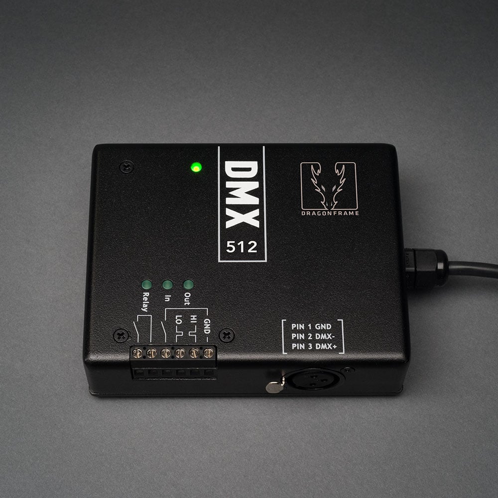
DDMX-512Advanced Lighting ControlAutomate lighting and interact with external devices using our DMX512 and digital I/O controller. Program scene/exposure lighting for advanced effects and automate bash lighting with ease. The DDMX-512 an updated version of our popular DDMX-S2, with support for 512 lighting channels, rather than the 99 provided by the DDMX-S2. Dragonframe 4 is required to access all 512 channels. With Dragonframe 3, the DDMX-512 will only provide 99 channels. This product is suitable for stop motion and time-lapse. For real-time DMX capabilities, you need our DMC-32 real-time controller instead. |
|
15 in stock |
DDMX-512 Lighting Control
Overview
The DDMX-512 is a hardware device that you can pair with Dragonframe to:
- Automate a work light (bash light) turning on and off.
- Automate front-light/back-light lighting passes.
- Automate keyframe-based lighting programs for your scene.
- Trigger a RED camera, film camera, or unsupported still camera.
- Trigger a motion control system for shoot-move-shoot integration.
- Trigger Dragonframe from an external system.
Control Lighting
DMX512 (or DMX) is a standard protocol for controlling lighting. When paired with one or more DMX dimmer/switch packs, you can control up to 512 different light channels.
Control Devices
Interact with external devices using the built-in relay switch, digital input and digital output.
What else do I need?
The DDMX-512 interfaces Dragonframe to one or more DMX dimmer/switch packs, or directly to DMX-enabled lights. For standard incandescent lights, you will need to buy a DMX dimmer/switch pack. Make sure that the one you choose can handle the power requirements of your lights. For LED lights, you must get ones that have DMX input or have a DMX-enabled controller.
You will also need a cable. You must use a cable designed for DMX, not a microphone cable. If you use a 5-pin DMX dimmer pack, you will need a 5-pin to 3-pin adapter.
Technical Specifications
Outputs
To prevent any possible damage to the host computer from badly grounded peripherals, all DDMX-512 outputs and inputs are optically isolated from the host USB bus. The I/O channels “float” electrically relative to the USB, thereby minimizing the opportunity for ground loops.
DMX out
DDMX-512 supports a USITT standard DMX512 output protocol. The DDMX-512 output will easily drive a standard 120 ohm bus termination.
The DMX channel provides packets of 512 slots, with a 50mS inter-packet period. The DMX port is typically equipped with a 3-pin XLR connector for easy connection to “entertainment” style DMX packs. To connect DDMX-512 to a USITT standard 5-pin XLR connector for use with “professional” style equipment, use a standard 3-pin to 5-pin adapter.
Relay out
The relay is intended to switch low-power control signals like button presses, but it can also switch small amounts of power. Do not exceed 0.5A @ 24VDC, or 0.25A @ 125VAC.
Logic out
Logic out is a standard 5V, TTL level, logic signal (relative to the ground terminal). The signal is provided in both active high and active low versions. Maximum load is 30mA in each state. These signals may also be used as a differential pair with a termination load greater than 220 ohms.
Switch in
Switch in is designed to sense a switch closure to ground. This input will also take a 5V TTL level signal. Note that in keeping with a switch closure, the logic on this pin is active low. This pin is internally pulled to 5V with a 1Kohm resister. When driving this pin externally, do not exceed 5 volts.
Physical Dimensions
4.7″ X 3.7″ X 1.3″ (12cm X 9cm X 3.5cm). Weight: approximately 12oz. (340g) with 5′ (1.5m) Type A USB pigtail. DDMX-512 is built ruggedly, in a .090″ thick cast aluminum box and painted with a hard powder coat to survive years in a harsh stage environment.
Power
DDMX-512 is a “high current” USB peripheral, drawing up to 220mA with all outputs active and fully loaded. As such it must be plugged directly into either a computer port or a powered USB hub. Your power source must provide at least 4.5 Volts. DDMX-512 should not be plugged into a unpowered USB hub. USB peripherals send their power requirements to the system on initialization, and unpowered hubs are supposed to reject peripherals that do not identify as “low current,” that is, any peripherals that require more than 100mA.

